|
S-8351
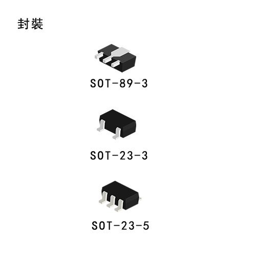
Super-Small Package PFM Control Step-Up Switching Regulator (DC/DC Converter ICs) S-8351/8352 Series Description The S-8351/8352 series is a CMOS PFM-control step-up switching regulator (DC/DC Converter ICs) that mainly consists of a reference voltage source, an oscillator, and a comparator. The PFM controller allows the duty ratio to be automatically switched according to the load (light load: 50%, high output current: 75%), enabling products with a low ripple over a wide range, high efficiency, and high output current (product types A, B, and D). Products with a fixed duty ratio of 75% are also available (product type C). With the S-8351 series, a step-up switching regulator (DC/DC Converter ICs) can be configured by using an external coil, capacitor, and diode. The built-in MOS FET is turned off by a protection circuit when the voltage at the CONT pin exceeds the limit to prevent it from being damaged. This feature, along with the mini package and low current consumption, makes the S-8351 series ideal for applications such as the power supply unit of portable equipment. The S-8352 series, which features an external transistor, is suitable for applications requiring a high output current.
Features
Applications
|
 S8351Ӣ��.pdf
|
S-8352
Super-Small Package PFM Control Step-Up Switching Regulator (DC/DC Converter ICs) S-8351/8352 Series Description The S-8351/8352 series is a CMOS PFM-control step-up switching regulator (DC/DC Converter ICs) that mainly consists of a reference voltage source, an oscillator, and a comparator. The PFM controller allows the duty ratio to be automatically switched according to the load (light load: 50%, high output current: 75%), enabling products with a low ripple over a wide range, high efficiency, and high output current (product types A, B, and D). Products with a fixed duty ratio of 75% are also available (product type C). With the S-8351 series, a step-up switching regulator (DC/DC Converter ICs) can be configured by using an external coil, capacitor, and diode. The built-in MOS FET is turned off by a protection circuit when the voltage at the CONT pin exceeds the limit to prevent it from being damaged. This feature, along with the mini package and low current consumption, makes the S-8351 series ideal for applications such as the power supply unit of portable equipment. The S-8352 series, which features an external transistor, is suitable for applications requiring a high output current.
Features
Applications
|

|
S-8353
Super-Small Package PWM Control, PWM/PFM Control Step-Up Switching Regulator (DC/DC Converter ICs) S-8353/8354 Series Description The S-8353/54 Series is a CMOS step-up switching regulator (DC/DC Converter ICs) which mainly consists of a reference voltage source, an oscillation circuit, a power MOS FET, an error amplifier, a phase compensation circuit, a PWM controller (S-8353) and a PWM/PFM switching controller (S-8354).The step-up switching regulator (DC/DC Converter ICs) can be configured simply by attaching a coil, capacitor, and diode externally. In addition to the above features, the small package and low power consumption of this series make it ideal for portable device applications requiring high efficiency.The S-8353 Series realizes low ripple, high efficiency, and excellent transient characteristics due to its PWM controller, which can vary the duty ratio linearly from 0% to 83% (from 0% to 78% for 250 kHz models), optimally-designed error amplifier, and phase compensation circuits. The S-8354 Series features a PWM/PFM switching controller that can switch the operation to a PFM controller with a duty ratio is 15% under a light load to prevent a decline in the efficiency due to the IC operating current.
Features
Applications
|

|
S-8354
Super-Small Package PWM Control, PWM/PFM Control Step-Up Switching Regulator (DC/DC Converter ICs) S-8353/8354 Series Description The S-8353/54 Series is a CMOS step-up switching regulator (DC/DC Converter ICs) which mainly consists of a reference voltage source, an oscillation circuit, a power MOS FET, an error amplifier, a phase compensation circuit, a PWM controller (S-8353) and a PWM/PFM switching controller (S-8354). The step-up switching regulator (DC/DC Converter ICs) can be configured simply by attaching a coil, capacitor, and diode externally. In addition to the above features, the small package and low power consumption of this series make it ideal for portable device applications requiring high efficiency. The S-8353 Series realizes low ripple, high efficiency, and excellent transient characteristics due to its PWM controller, which can vary the duty ratio linearly from 0% to 83% (from 0% to 78% for 250 kHz models), optimally-designed error amplifier, and phase compensation circuits. The S-8354 Series features a PWM/PFM switching controller that can switch the operation to a PFM controller with a duty ratio is 15% under a light load to prevent a decline in the efficiency due to the IC operating current.
Features
Applications
|
|
S-8363
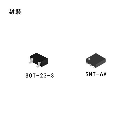
Step-up, Super-small Package, 1.2 MHz PWM / PFM Switchable Switchin Regulator S-8363 Series Description The S-8363 Series is a CMOS step-up switching regulator which consists of a referencevoltage source, an oscillation circuit, an error amplifier, a phase compensation circuit, a current limit circuit, and a start-up circuit. Due to the operation of the PWM / PFM switching control, pulses are skipped under the light load operation and the S-8363 Series prevents decrease in efficiency caused by IC��s operating current. The S-8363 Series is capable of start-up from 0.9 V (Iout = 1 mA) by the start-up circuit, and is suitable for applications which use one dry cell. The output voltage is freely settable from 1.8 V to 5.0 V by external parts. Ceramic capacitors can be used for output capacitor. Small packages SNT-6A and SOT-23-6 enable high-density mounting.
Features
Applications
|

|
S-8355
Super-Small Package PWM Control, PWM/PFM Control Step-Up Switching Regulator (DC/DC Converter ICs) S-8355/56/57/58 Series Description The S-8355/56/57/58 Series is a CMOS step-up switching regulator (DC/DC Converter ICs) which mainly consists of a reference voltage source, an oscillation circuit, an error amplifier, a phase compensation circuit, a PWM control circuit (S-8355/57) and a PWM/PFM switching control circuit (S-8356/58). With an external low-ON-resistance Nch Power MOS, this product is applicable to applications requiring high efficiency and high output current. The S-8355/57 Series realizes low ripple, high efficiency, and excellent transient characteristics with the PWM control circuit whose duty ratio can vary from 0 % to 83 % (from 0 % to 78 % for 250 kHz and 300 kHz models), the best-designed error amplifier and phase compensation circuits. The S-8356/58 Series switches its operation to the PFM control circuit whose duty ratio is 15 % with to the PWM/PFM switching control circuit under a light load and to prevent decline in the efficiency by IC operation current.
Features
Applications
|
|
S-8356
Super-Small Package PWM Control, PWM/PFM Control Step-Up Switching Regulator (DC/DC Converter ICs) S-8355/56/57/58 Series Description The S-8355/56/57/58 Series is a CMOS step-up switching regulator (DC/DC Converter ICs) which mainly consists of a reference voltage source, an oscillation circuit, an error amplifier, a phase compensation circuit, a PWM control circuit (S-8355/57) and a PWM/PFM switching control circuit (S-8356/58). With an external low-ON-resistance Nch Power MOS, this product is applicable to applications requiring high efficiency and high output current. The S-8355/57 Series realizes low ripple, high efficiency, and excellent transient characteristics with the PWM control circuit whose duty ratio can vary from 0 % to 83 % (from 0 % to 78 % for 250 kHz and 300 kHz models), the best-designed error amplifier and phase compensation circuits. The S-8356/58 Series switches its operation to the PFM control circuit whose duty ratio is 15 % with to the PWM/PFM switching control circuit under a light load and to prevent decline in the efficiency by IC operation current.
Features
Applications
|

|
S-8357
Super-Small Package PWM Control, PWM/PFM Control Step-Up Switching Regulator (DC/DC Converter ICs) S-8355/56/57/58 Series Description The S-8355/56/57/58 Series is a CMOS step-up switching regulator (DC/DC Converter ICs) which mainly consists of a reference voltage source, an oscillation circuit, an error amplifier, a phase compensation circuit, a PWM control circuit (S-8355/57) and a PWM/PFM switching control circuit (S-8356/58). With an external low-ON-resistance Nch Power MOS, this product is applicable to applications requiring high efficiency and high output current. The S-8355/57 Series realizes low ripple, high efficiency, and excellent transient characteristics with the PWM control circuit whose duty ratio can vary from 0 % to 83 % (from 0 % to 78 % for 250 kHz and 300 kHz models), the best-designed error amplifier and phase compensation circuits. The S-8356/58 Series switches its operation to the PFM control circuit whose duty ratio is 15 % with to the PWM/PFM switching control circuit under a light load and to prevent decline in the efficiency by IC operation current.
Features
Applications
|

|
S-8358
Super-Small Package PWM Control, PWM/PFM Control Step-Up Switching Regulator (DC/DC Converter ICs) S-8355/56/57/58 Series Description The S-8355/56/57/58 Series is a CMOS step-up switching regulator (DC/DC Converter ICs) which mainly consists of a reference voltage source, an oscillation circuit, an error amplifier, a phase compensation circuit, a PWM control circuit (S-8355/57) and a PWM/PFM switching control circuit (S-8356/58). With an external low-ON-resistance Nch Power MOS, this product is applicable to applications requiring high efficiency and high output current. The S-8355/57 Series realizes low ripple, high efficiency, and excellent transient characteristics with the PWM control circuit whose duty ratio can vary from 0 % to 83 % (from 0 % to 78 % for 250 kHz and 300 kHz models), the best-designed error amplifier and phase compensation circuits. The S-8356/58 Series switches its operation to the PFM control circuit whose duty ratio is 15 % with to the PWM/PFM switching control circuit under a light load and to prevent decline in the efficiency by IC operation current.
Features
Applications
|

|
S-8365
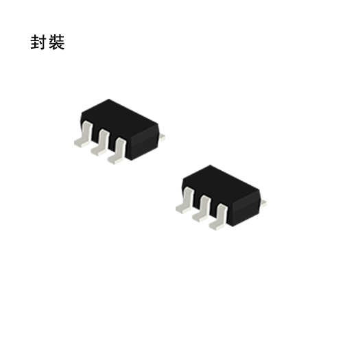
Step-Up, Super-Small Package, 1.2 MHz PWM Control or PWM/PFM Switchable Switching Regulator Controller S-8365/8366 Series Description The S-8365/8366 Series is a CMOS step-up switching regulator controller which mainly consists of a reference voltage source, an oscillation circuit, an error amplifier, a phase compensation circuit, a timer latch short-circuit protection circuit, a PWM control circuit (S-8365 Series) and a PWM / PFM switching control circuit (S-8366 Series). With an external low-ON-resistance Nch Power MOS, this product is ideal for applications requiring high efficiency and a high output current. The S-8365 Series efficiently works on voltage��s condition of large I/O difference due to the PWM control circuit linearly varies the duty ratio to 90%. During light-load, the S-8366 Series switches its operation to the PFM control by the PWM / PFM switching control circuit in order to prevent efficiency decline due to the IC operating current. Ceramic capacitors can be used for output capacitor. Small packages SNT-6A, SOT-23-5 and SOT-23-6 enable high-density mounting.
Features
Applications
|

|
S-8366
Step-Up, Super-Small Package, 1.2 MHz PWM Control or PWM/PFM Switchable Switching Regulator Controller S-8365/8366 Series Description The S-8365/8366 Series is a CMOS step-up switching regulator controller which mainly consists of a reference voltage source, an oscillation circuit, an error amplifier, a phase compensation circuit, a timer latch short-circuit protection circuit, a PWM control circuit (S-8365 Series) and a PWM / PFM switching control circuit (S-8366 Series). With an external low-ON-resistance Nch Power MOS, this product is ideal for applications requiring high efficiency and a high output current. The S-8365 Series efficiently works on voltage��s condition of large I/O difference due to the PWM control circuit linearly varies the duty ratio to 90%. During light-load, the S-8366 Series switches its operation to the PFM control by the PWM / PFM switching control circuit in order to prevent efficiency decline due to the IC operating current. Ceramic capacitors can be used for output capacitor. Small packages SNT-6A, SOT-23-5 and SOT-23-6 enable high-density mounting.
Features
Applications
|

|
S-8340
PWM Control & PWM/PFM Control High Frequency Step-Up Switching Regulator (DC/DC Converter ICs) S-8340/8341 Series Description The S-8340/8341 series consists of CMOS step-up switching regulator (DC/DC Converter ICs)-controllers with PWM control (S-8340) and PWM/PFM switched control (S-8341). These devices contain a reference voltage source, oscillation circuit, error amplifier, phase compensation circuit, PWM control circuit, and other components. Since the oscillation frequency is a high 300 kHz or 600 kHz, with the addition of a small external component, the ICs can function as step-up switching regulators with high efficiency and large output current. The speed of the output stage is enhanced so that the Nch power MOS with a low ON resistance can be switched quickly.
Features
Applications
|

|
S-8341
PWM Control & PWM/PFM Control High Frequency Step-Up Switching Regulator (DC/DC Converter ICs) S-8340/8341 Series Description The S-8340/8341 series consists of CMOS step-up switching regulator (DC/DC Converter ICs)-controllers with PWM control (S-8340) and PWM/PFM switched control (S-8341). These devices contain a reference voltage source, oscillation circuit, error amplifier, phase compensation circuit, PWM control circuit, and other components. Since the oscillation frequency is a high 300 kHz or 600 kHz, with the addition of a small external component, the ICs can function as step-up switching regulators with high efficiency and large output current. The speed of the output stage is enhanced so that the Nch power MOS with a low ON resistance can be switched quickly.
Features
Applications
|
|
S-8333
Step-up, for LCD Bias Supply, 1-channel, PWM Control Switching Regulator Controller S-8333 Series Description The S-8333 Series is a CMOS step-up switching regulator which mainly consists of a reference voltage circuit, an oscillator, an error amplifier, a PWM controller, an under voltage lockout circuit (UVLO), and a timer latch short-circuit protection circuit. Because its minimum operating voltage is as low as 1.8 V, this switching regulator is ideal for the power supply of an LCD or for portable systems that operate on a low voltage. The internal oscillation frequency can be set up to 1.08 MHz, via the resistor connected to the ROSC pin. The maximum duty ratio of PWM control can be controlled by the resistor connected to the RDuty pin. The soft-start function at power application is accomplished by combining the reference voltage control and maximum duty control methods. Even if the voltage of the FB pin is retained lower than the reference voltage due to the factor outside the IC, the output voltage is raised by controlling the maximum duty. The phase compensation and gain value can be adjusted according to the values of the resistor and capacitor connected to the CC pin. Therefore, the operation stability and transient response can be correctly set for each application. The reference voltage accuracy is as high as 1.0 V ��1.5%, and any voltage can be output by using an external output voltage setting resistor. In addition, the delay time of the short-circuit protection circuit can be set by using the capacitor connected to the CSP pin. If the maximum duty condition continues because of short-circuiting, the capacitor externally connected to the CSP pin is charged, and oscillation stops after a specific time. The short-circuit protection function is cancelled when the power supply is raised to the UVLO release voltage after it has been lowered to the UVLO detection voltage. A ceramic capacitor or a tantalum capacitor is used as the output capacitor, depending on the setting. This controller IC allows various settings and selections and employs a small
Features
Applications
|
|
S-8337
Step-up High-frequency, PWM Control Switching Regulator (DC/DC Converter ICs) Controllers S-8337/8338 Series Description The S-8337/38 series is a CMOS step-up switching regulator (DC/DC Converter ICs) which mainly consists of a reference voltage circuit, an oscillator, an error amplifier, a PWM controller, an under voltage lockout circuit (UVLO), and a timer latch short-circuit protection circuit. Because its minimum operating voltage is as low as 1.8 V, this switching regulator (DC/DC Converter ICs) is ideal for the power supply of an LCD or for portable systems that operate on a low voltage. The internal oscillation frequency can be set up to 1.133 MHz, via the resistor connected to the ROSC pin. With the S-8337 series, the maximum duty ratio of PWM control can be controlled by the resistor connected to the RDuty pin. With the S-8338 series, the maximum duty ratio is fixed (to 88%). The phase compensation and gain value can be adjusted according to the values of the resistor and capacitor connected to the CC pin. Therefore, the operation stability and transient response can be correctly set for each application. The reference voltage accuracy is as high as 1.0 V ��1.5%, and any voltage can be output by using an external output voltage setting resistor. In addition, the delay time of the short-circuit protection circuit can be set by using the capacitor connected to the CSP pin. If the maximum duty condition continues because of short-circuiting, the capacitor externally connected to the CSP pin is charged, and oscillation stops after a specific time. This condition is cleared by re-application of power or by setting the switching regulator(DC/DC Converter ICs) (S-8338 series) to the shutdown status. A ceramic capacitor or a tantalum capacitor is used as the output capacitor, depending on the setting. This controller IC allows various settings and selections and employs a small package, making it very easy to use.
Features
Applications
|

|
S-8338
Step-up High-frequency, PWM Control Switching Regulator (DC/DC Converter ICs) Controllers S-8337/8338 Series Description The S-8337/38 series is a CMOS step-up switching regulator (DC/DC Converter ICs) which mainly consists of a reference voltage circuit, an oscillator, an error amplifier, a PWM controller, an under voltage lockout circuit (UVLO), and a timer latch short-circuit protection circuit. Because its minimum operating voltage is as low as 1.8 V, this switching regulator (DC/DC Converter ICs) is ideal for the power supply of an LCD or for portable systems that operate on a low voltage. The internal oscillation frequency can be set up to 1.133 MHz, via the resistor connected to the ROSC pin. With the S-8337 series, the maximum duty ratio of PWM control can be controlled by the resistor connected to the RDuty pin. With the S-8338 series, the maximum duty ratio is fixed (to 88%). The phase compensation and gain value can be adjusted according to the values of the resistor and capacitor connected to the CC pin. Therefore, the operation stability and transient response can be correctly set for each application. The reference voltage accuracy is as high as 1.0 V ��1.5%, and any voltage can be output by using an external output voltage setting resistor. In addition, the delay time of the short-circuit protection circuit can be set by using the capacitor connected to the CSP pin. If the maximum duty condition continues because of short-circuiting, the capacitor externally connected to the CSP pin is charged, and oscillation stops after a specific time. This condition is cleared by re-application of power or by setting the switching regulator(DC/DC Converter ICs) (S-8338 series) to the shutdown status. A ceramic capacitor or a tantalum capacitor is used as the output capacitor, depending on the setting. This controller IC allows various settings and selections and employs a small package, making it very easy to use.
Features
Applications
|
|
S-8550
Step-Down, Built-in FET, Synchronous Rectification, PWM Control Switching Regulator (DC/DC Converter ICs) S-8550 Series Description The S-8550 Series is a CMOS synchronous rectification step-down switching regulator which mainly consists of a reference voltage circuit, an oscillator, an error amplifier, a phase compensation circuit, a PWM controller, an under voltage lockout circuit (UVLO), a current limit circuit, and a power MOS FET. The oscillation frequency is high at 1.2 MHz, so a high efficiency, large output current, step-down switching regulator can be achieved by using small external parts. The built-in synchronous rectification circuit makes achieving high efficiency easier compared with conventional step-down switching regulators. A ceramic capacitor can be used as an output capacitor. High-density mounting is supported by adopting packages small SOT-23-5 and super-small and thin SNT-8A.
Features
Applications
|

|
S-8520
PWM Control & PWM/PFM Control Step-Down Switching Regulator (DC/DC Converter ICs) S-8520/8521 Series Description The S-8520/8521 series consists of CMOS step-down switching regulator (DC/DC Converter ICs)-controllers with PWM-control (S-8520) and PWM/PFM-switched control (S-8521). These devices contain a reference voltage source, oscillation circuit, error amplifier, and other components. Features
Applications
|

|
S-8521
PWM Control & PWM/PFM Control Step-Down Switching Regulator (DC/DC Converter ICs) S-8520/8521 Series Description The S-8520/8521 series consists of CMOS step-down switching regulator (DC/DC Converter ICs)-controllers with PWM-control (S-8520) and PWM/PFM-switched control (S-8521). These devices contain a reference voltage source, oscillation circuit, error amplifier, and other components. Features
Applications
|

|
S-8540
PWM Control & PWM/PFM Control High Frequency Step-Down Switching Regulator (DC/DC Converter ICs) S-8540/8541 Series Description The S-8540/8541 series is a family of CMOS step-down switching regulator (DC/DC Converter ICs) controllers with PWM control (S-8540) and PWM/PFM switchover control (S-8541). These devices consist of a reference voltage source, oscillation circuit, an error amplifier, phase compensation circuit, PWM control circuit, current limit circuit. A high efficiency and large current switching regulator (DC/DC Converter ICs) is realized with the help of small external components due to the high oscillation frequency, 300 kHz and 600 kHz. The S-8540 provides low-ripple voltage, high efficiency, and excellent transient characteristics which come form the PMW control circuit capable of varying the duty ratio linearly from 0% to 100%, the optimized error amplifier, and the phase compensation circuit. The S-8541 operates under PWM control when the duty ratio is 29% or higher and operates under PFM control when the duty ratio is less than 29% to ensure high efficiency over all load range. These controllers serve as ideal main power supply units for portable devices due to the high oscillation frequencies together with the small 8-pin MSOP package.
Features
Applications
|

|
S-8541
PWM Control & PWM/PFM Control High Frequency Step-Down Switching Regulator (DC/DC Converter ICs) S-8540/8541 Series Description The S-8540/8541 series is a family of CMOS step-down switching regulator (DC/DC Converter ICs) controllers with PWM control (S-8540) and PWM/PFM switchover control (S-8541). These devices consist of a reference voltage source, oscillation circuit, an error amplifier, phase compensation circuit, PWM control circuit, current limit circuit. A high efficiency and large current switching regulator (DC/DC Converter ICs) is realized with the help of small external components due to the high oscillation frequency, 300 kHz and 600 kHz. The S-8540 provides low-ripple voltage, high efficiency, and excellent transient characteristics which come form the PMW control circuit capable of varying the duty ratio linearly from 0% to 100%, the optimized error amplifier, and the phase compensation circuit. The S-8541 operates under PWM control when the duty ratio is 29% or higher and operates under PFM control when the duty ratio is less than 29% to ensure high efficiency over all load range. These controllers serve as ideal main power supply units for portable devices due to the high oscillation frequencies together with the small 8-pin MSOP package.
Features
Applications
|
|
S-8533
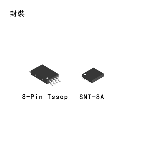
Synchronous PWM Control Step-Down Switching Regulator (DC/DC Converter ICs) S-8533 Series Description The S-8533 series is a synchronous PWM control CMOS step-down switching regulator (DC/DC Converter ICs) controller that includes a reference voltage source, synchronous circuit, an oscillation circuit, an error amplifier, a phase compensation circuit, and a PWM controller. An efficient step-down switching regulator (DC/DC Converter ICs) can be realized simply by adding external Pch and Nch power MOSFETs, one coil, and three capacitors. Since the oscillation frequency is a high 300 kHz, the S-8533 can be used to configure a high efficiency step-down switching regulator (DC/DC Converter ICs) capable of driving high output current using small external components and a 3 to 10% in-crease in efficiency is obtained compared to conventional step-down switching regulators(DC/DC Converter ICs). The 8-Pin TSSOP and high oscillation frequency make the S-8533 ideal as the main power supply for portable devices.
Features
Applications
|
|
S-85S0P
Supply Voltage Divided Output, 5.5 V Input, 50 mA Synchronous Step-down switching Regulator with 260 nA Quiescent Current S-85S0P Series Describe: The S-85S0P Series introduces own distinctive low power consumption control and COT (Constant On-Time) control, features ultra low current consumption (260 nA quiescent current) and fast transient response, operates at PFM control. The S-85S0P Series realizes high efficiency in a wide range of load current consumption and provides strong support forextended period operation of mobile devices and wearable devices which are equipped with compact batteries. Features: DC-DC converter block • Ultra low current consumption: 260 nA quiescent current • Efficiency (when under 100 ��A load): 90.5% • Fast transient response: COT control • Input voltage: 2.2 V to 5.5 V • Output voltage: 0.7 V to 2.5 V, in 0.05 V step 2.6 V to 3.9 V, in 0.1 V step • Output voltage accuracy: ��1.5% (1.0 V �� VOUT �� 3.9 V) ��15 mV (0.7 V �� VOUT < 1.0 V) • High side power MOS FET on-resistance: 420 m�� • Low side power MOS FET on-resistance: 320 m�� • Soft-start function: 1 ms typ. • Under voltage lockout function (UVLO): 1.8 V typ. (detection voltage) • Thermal shutdown function: 135��C typ. (detection temperature) • Overcurrent protection function: 300 mA (at L = 2.2 ��H) • Automatic recovery type short-circuit protection function: Hiccup control • Input and output capacitors: Ceramic capacitor compatible Supply voltage divider block • Low current consumption: 280 nA typ. • Input voltage: 1.5 V to 5.5 V • Output voltage: VIN/2 (S-85S0PCxx) VIN/3 (S-85S0PDxx) Overall • Operation temperature range: Ta = −40��C to +85��C • Lead-free (Sn 100%), halogen-free Applications: • Wearable device • Bluetooth device • Wireless sensor network device • Healthcare equipment • Smart meter • Portable game device |

|
S-85S1P
Supply Voltage Divided Output, 5.5 V Input, 200 mA Synchronous Step-down Switching Regulator with 260 nA Quiescent Current S-85S1P Series Describe: The S-85S1P Series introduces own distinctive low power consumption control and COT (Constant On-Time) control and features ultra low current consumption and fast transient response. PWM / PFM switching control automatically switches to PFM control when under light load, and the IC operates at ultra low current consumption of 260 nA quiescent current. The S-85S1P Series realizes high efficiency in a wide range of load current consumption and provides strong support for extended period operation of mobile devices and wearable devices which are equipped with compact batteries. Features: DC-DC converter block • Ultra low current consumption: 260 nA quiescent current • Efficiency (when under 100 ��A load): 90.5% • Fast transient response: COT control • Input voltage: 2.2 V to 5.5 V • Output voltage: 0.7 V to 2.5 V, in 0.05 V step 2.6 V to 3.9 V, in 0.1 V step • Output voltage accuracy: ��1.5% (1.0 V �� VOUT �� 3.9 V) ��15 mV (0.7 V �� VOUT < 1.0 V) • Switching frequency: 1.0 MHz (at PWM operation) • High side power MOS FET on-resistance: 420 m�� • Low side power MOS FET on-resistance: 320 m�� • Soft-start function: 1 ms typ. • Under voltage lockout function (UVLO): 1.8 V typ. (detection voltage) • Thermal shutdown function: 135��C typ. (detection temperature) • Overcurrent protection function: 450 mA (at L = 2.2 ��H) • Automatic recovery type short-circuit protection function:Hiccup control • Input and output capacitors: Ceramic capacitor compatible Supply voltage divider block • Low current consumption: 280 nA typ. • Input voltage: 1.5 V to 5.5 V • Output voltage: VIN/2 (S-85S1PCxx) VIN/3 (S-85S1PDxx) Overall • Operation temperature range: Ta = −40��C to +85��C • Lead-free (Sn 100%), halogen-free Applications: • Wearable device • Bluetooth device • Wireless sensor network device • Healthcare equipment • Smart meter • Portable game device |

|
S-85S0A
5.5 V Input, 50 mA Synchronous Step-Down Switching Regulator with 260 nA Quiescent Current S-85S0A Series Describe: The S-85S0A Series introduces own distinctive low power consumption control and COT (Constant On-Time) control, features ultra low current consumption (260 nA quiescent current) and fast transient response, operates at PFM control. The S-85S0A Series realizes high efficiency in a wide range of load current consumption and provides strong support for extended period operation of mobile devices and wearable devices which are equipped with compact batteries. Features: • Ultra low current consumption: 260 nA quiescent current • Efficiency (when under 100 ��A load): 90.5% • Fast transient response: COT control • Input voltage: 2.2 V to 5.5 V • Output voltage: 0.7 V to 2.5 V, in 0.05 V stepr 2.6 V to 3.9 V, in 0.1 V step • Output voltage accuracy: ��1.5% (1.0 V �� VOUT �� 3.9 V) ��15 mV (0.7 V �� VOUT < 1.0 V) • High side power MOS FET on-resistance: 420 m�� • Low side power MOS FET on-resistance: 320 m�� • Soft-start function: 1 ms typ. • Under voltage lockout function (UVLO): 1.8 V typ. (detection voltage) • Thermal shutdown function: 135��C typ. (detection temperature) • Overcurrent protection function: 300 mA (at L = 2.2 ��H) • Automatic recovery type short-circuit protection function:Hiccup control • Input and output capacitors: Ceramic capacitor compatible • Operation temperature range: Ta = −40��C to +85��C • Lead-free (Sn 100%), halogen-free Applications: • Wearable device • Bluetooth device • Wireless sensor network device • Healthcare equipment • Smart meter • Portable game device |
|
S-85S1A
5.5v Input, 200mA Synchronous Step-Down Switching Regulator with 260nA Quiescent Current S-85S1A Series Describe: The S-85S1A Series introduces own distinctive low power consumption control and COT (Constant On-Time) control and features ultra low current consumption and fast transient response. PWM / PFM switching control automatically switches to PFM control when under light load, and the IC operates at ultra low current consumption of 260 nA quiescent current. The S-85S1A Series realizes high efficiency in a wide range of load current consumption and provides strong support for extended period operation of mobile devices and wearable devices which are equipped with compact batteries. Features: • Ultra low current consumption: 260 nA quiescent current • Efficiency (when under 100 ��A load): 90.5% • Fast transient response: COT control • Input voltage: 2.2 V to 5.5 V • Output voltage: 0.7 V to 2.5 V, in 0.05 V step 2.6 V to 3.9 V, in 0.1 V step • Output voltage accuracy: ��1.5% (1.0 V �� VOUT �� 3.9 V) ��15 mV (0.7 V �� VOUT < 1.0 V) • Switching frequency: 1.0 MHz (at PWM operation) • High side power MOS FET on-resistance: 420 m�� • Low side power MOS FET on-resistance: 320 m�� • Soft-start function: 1 ms typ. • Under voltage lockout function (UVLO): 1.8 V typ. (detection voltage) • Thermal shutdown function: 135��C typ. (detection temperature) • Overcurrent protection function: 450 mA (at L = 2.2 ��H) • Automatic recovery type short-circuit protection function:Hiccup control • Input and output capacitors: Ceramic capacitor compatible • Operation temperature range: Ta = −40��C to +85��C • Lead-free (Sn 100%), halogen-free Applications: • Wearable device • Bluetooth device • Wireless sensor network device • Healthcare equipment • Smart meter • Portable game device |
|
S-85M0A
5.6 V Input, 50 mA, Low EMI, Synchronous Step-down Switching Regulator with 260 nA Quiescent Current S-85M0A Series (WLP product) Describe: The S-85M0A Series introduces own distinctive low power consumption control and COT (Constant On-Time) control, features ultra low current consumption (260 nA quiescent current) and fast transient response, operates at PFM control. The S-85M0A Series realizes high efficiency in a wide range of load current consumption and provides strong support for extended period operation of mobile devices and wearable devices which are equipped with compact batteries. Features: • Ultra low current consumption: 260 nA quiescent current • Efficiency (when under 100 ��A load): 90.5% • Fast transient response: COT control • Input voltage: 2.2 V to 5.6 V • Output voltage: 0.7 V to 2.5 V, in 0.05 V step 2.6 V to 3.9 V, in 0.1 V step • Output voltage accuracy: ��1.5% (1.0 V �� VOUT �� 3.9 V) ��15 mV (0.7 V �� VOUT < 1.0 V) • High side power MOS FET on-resistance: 360 m�� • Low side power MOS FET on-resistance: 250 m�� • Soft-start function: 1 ms typ. • Under voltage lockout function (UVLO): 1.8 V typ. (detection voltage) • Thermal shutdown function: 135��C typ. (detection temperature) • Overcurrent protection function: 300 mA (at L = 2.2 ��H) • Automatic recovery type short-circuit protection function: Hiccup control • Discharge shunt function: Unavailable (S-85M0A Series B type) Available (S-85M0A Series C type) • Input and output capacitors: Ceramic capacitor compatible • Operation temperature range: Ta = −40��C to +85��C • Lead-free, halogen-free Applications: • Wearable device • Bluetooth device • Wireless sensor network device • Healthcare equipment • Smart meter • Portable game device • GPS device |

|
S-85M1A
5.6 V Input, 200 mA, Low EMI, Synchronous Step-down Switching Regulator with 260 nA Quiescent Current S-85M1A Series (WLP product) Describe: The S-85M1A Series introduces own distinctive low power consumption control and COT (Constant On-Time) control and features ultra low current consumption and fast transient response. PWM / PFM switching control automatically switches to PFM control when under light load, and the IC operates at ultra low current consumption of 260 nA quiescent current. The S-85M1A Series realizes high efficiency in a wide range of load current consumption and provides strong support for extended period operation of mobile devices and wearable devices which are equipped with compact batteries. Features: • Ultra low current consumption: 260 nA quiescent current • Efficiency (when under 100 ��A load): 90.5% • Fast transient response: COT control • Input voltage: 2.2 V to 5.6 V • Output voltage: 0.7 V to 2.5 V, in 0.05 V step 2.6 V to 3.9 V, in 0.1 V step • Output voltage accuracy: ��1.5% (1.0 V �� VOUT �� 3.9 V) ��15 mV (0.7 V �� VOUT < 1.0 V) • Switching frequency: 1.0 MHz (at PWM operation) • High side power MOS FET on-resistance: 360 m�� • Low side power MOS FET on-resistance: 250 m�� • Soft-start function: 1 ms typ. • Under voltage lockout function (UVLO): 1.8 V typ. (detection voltage) • Thermal shutdown function: 135��C typ. (detection temperature) • Overcurrent protection function: 450 mA (at L = 2.2 ��H) • Automatic recovery type short-circuit protection function: Hiccup control • Discharge shunt function: Unavailable (S-85M1A Series B type) Available (S-85M1A Series C type) • Input and output capacitors: Ceramic capacitor compatible • Operation temperature range: Ta = −40��C to +85��C • Lead-free, halogen-free Applications: • Wearable device • Bluetooth device • Wireless sensor network device • Healthcare equipment • Smart meter • Portable game device • GPS device |
|
S-8580AC/ S-8580AD/ S-8581AC/ S-8581AD
36V Input, 600 mA Synchronous Step-Down Switching Regulator S-8580AC/ S-8580AD/ S-8581AC/ S-8581AD Series Describe: The S-8580/8581 Series is a step-down switching regulator developed using high withstand voltage CMOS process technologies. This IC has high maximum operation voltage of 36 V and maintains high-accuracy FB pin voltage at ��1.5%. As suitable packages for high-density mounting, such as small-sized HSNT-6(2025), are adopted, this IC contributes to miniaturization of electronic equipment. PWM control (S-8580 Series) or PWM / PFM switching control (S-8581 Series) can be selected as an option. Since the S-8581 Series, which features PWM / PFM switching control, operates with PWM control under heavy load and automatically switches to PFM control under light load, it achieves high-efficiency operation in accordance with the device��s status. Furthermore, our distinctive PWM / PFM switching control technology suppresses the ripple voltage to be generated in VOUT while PFM control is in operation. Since the S-8580/8581 Series has the built-in synchronous circuit, it achieves high efficiency easier compared with conventional step-down switching regulators. In addition, it has the built-in overcurrent protection circuit which protects the IC and coils from excessive load current as well as a thermal shutdown circuit which prevents damage from heat generation. Features: • Input voltage: 4.0 V to 36.0 V • Output voltage (externally set): 2.5 V to 12.0 V for industrial equipment • Output current: 600 mA • FB pin voltage accuracy: ��1.5% for home electric appliance • Efficiency: 95% • Oscillation frequency: 400 kHz typ. • Overcurrent protection function: 1.2 A typ. (pulse-by-pulse method) • Thermal shutdown function: 170��C typ. (detection temperature) • Short-circuit protection function: Hiccup control, Latch control • 100% duty cycle operation: • Soft-start function: 5.8 ms typ. • Under voltage lockout function (UVLO): 3.35 V typ. (detection voltage) • Input and output capacitors: Ceramic capacitor compatible • Operation temperature range: Ta = −40��C to +85��C • Lead-free (Sn 100%), halogen-free Applications: • Constant-voltage power supply for industrial equipment • Constant-voltage power supply for home electric appliance |

|
S-8580AA/S-8580AB/S-8581AA/S-8581AB
36V Input, 600 mA Synchronous Step-Down Switching Regulator S-8580AA/S-8580AB/S-8581AA/S-8581AB Series Describe: The S-8580/8581 Series is a step-down switching regulator developed using high withstand voltage CMOS process technologies. This IC has high maximum operation voltage of 36 V and maintains high-accuracy FB pin voltage at ��1.5%. As suitable packages for high-density mounting, such as small-sized HSNT-6(2025), are adopted, this IC contributes to miniaturization of electronic equipment. PWM control (S-8580 Series) or PWM / PFM switching control (S-8581 Series) can be selected as an option. Since the S-8581 Series, which features PWM / PFM switching control, operates with PWM control under heavy load and automatically switches to PFM control under light load, it achieves high-efficiency operation in accordance with the device��s status. Furthermore, our distinctive PWM / PFM switching control technology suppresses the ripple voltage to be generated in VOUT while PFM control is in operation. Since the S-8580/8581 Series has the built-in synchronous circuit, it achieves high efficiency easier compared with conventional step-down switching regulators. In addition, it has the built-in overcurrent protection circuit which protects the IC and coils from excessive load current as well as a thermal shutdown circuit which prevents damage from heat generation. Features: • Input voltage: 4.0 V to 36.0 V • Output voltage (externally set): 2.5 V to 30.0 V (S-8580 Series) for industrial equipment 2.5 V to 12.0 V (S-8581 Series) • Output current: 600 mA • FB pin voltage accuracy: ��1.5% for home electric appliance • Efficiency: 91% • Oscillation frequency: 2.2 MHz typ. • Overcurrent protection function: 1.2 A typ. (pulse-by-pulse method) • Thermal shutdown function: 170��C typ. (detection temperature) • Short-circuit protection function: Hiccup control, Latch control • 100% duty cycle operation: • Soft-start function: 5.8 ms typ. • Under voltage lockout function (UVLO): 3.35 V typ. (detection voltage) • Input and output capacitors: Ceramic capacitor compatible • Operation temperature range: Ta = −40��C to +85��C • Lead-free (Sn 100%), halogen-free Applications: • Constant-voltage power supply for industrial equipment • Constant-voltage power supply for home electric appliance |