Technical article
Sensing current of DC/DC converter
Sensing current of DC/DC converter
Micro processor requires larger current at lower voltage as the speed rises higher. A Desk Top Computer needs 40-60Amps, and even a notebook PC often demands more than 20Amps.
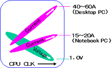
Trends of resistor for current sensing
Resistance is decreased to measure an increased current.
The resistance may be less than 2m.Some additional consideration is necessary for applications of such resistors.
When the Resistance is very low,
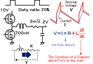
It becomes difficult to "sense the voltage precisely proportional to the current that flows through a resistor", which is a fundamental function of a resistor, when the switching frequency exceeds 100KHz(1)Minimize the inductance of resistor and PCB pattern
Parasitic inductance on a resistor normally ranges around several nH and it is negligibly small for frequencies up to several 100KHz. But for an extremely low value resistor, minute inductance affects relatively large impedance to cause an error to the resistance.
Example of the error by inductance
An example is shown below. Parasitic inductance is assumed to be 1 nH in this figure.
Trimming disturbs the current flow
A resistor is trimmed to form a slit to adjust resistance.
This may cause a non-uniformity to the current flow, and may result in a heat spot. Local heating may aggravate the linearity of resistance vs. current.
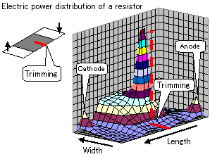
(2)Resistivity should be uniform;
Not only a trimming line but voids at the junction with the resistor and the electrode might cause non-uniformity of current density.
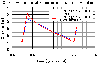
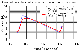
Tolerance of parasitic inductance might result in��
An error in the measurement, while error compensation may be possible for a fixed value. Influence from inductance can be contained in some degree by the use of filter. But scatter in parasitic inductance will also result in scatter of detected current values. In the figures below, simulations of the scatter of detected current values are shown.
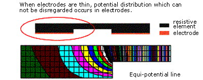
(3)Electric potential across electrodes must be consistent;
The ratio of resistivity of electrode to that of resistive material is as small as several dozens for ultra low resistance. When the electrode is not thick enough, it cannot keep equi-potential regardless of the non-uniformity of current density inside the resistor. This means depending on where in the electrode voltage is extracted, resistance value varies.
Selection guide for current sensing resistor:
From the above discussion, current sensing resistor for large current should be:
(1) Minimum parasitic inductance and minimum tolerance
(2) Uniform structure of resistor and electrode
(3)Minimum potential difference across electrode
Uniform the current flow inside the resistor
Above conditions are achieved by completely getting rid of factors spoiling uniformity.
Metal plate type resistor TLR, is developed under this concept.
�ص�
Ultra low resistances (0.5m����), suitable for large current sensing
Ultra low height with a thickness of 0.6mm, suitable for useof small equipment.
Excellent high-frequency characteristics
Automatic mounting machines are applicable.
Suitable for reflow soldering. (Not suitable for flow soldering)
Products meet EU-RoHS requirements.
AEC-Q200 qualified.
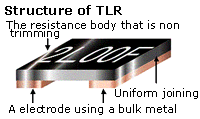
Actual structure of TLR
The structure of TLR is shown. It has a flat resistive metal plate with bulk electrodes on it. Trimming is given not by slitting but by shaving the width of the plate as to keep uniformity. Thus the TLR is suitable to sense the current of DC/DC converters.
Additional comments:
The following considerations are still more necessary:
(1)Fluctuation of detection in multi-phase DC/DC converter
(2)PCB pattern design including current and voltage pads
(3)Heat dissipation
(4)Filter to minimize sensing errors